| |
|
Click an image to enlarge. |
 A
modern car's engine control unit (ECU) handles so many variables and
there are so many modifications now available that using an engine
management system (EMS) makes more sense than ever. There are many
systems with different strengths and weaknesses. On the simpler side
is the AccessPort. You can download performance maps for your specific
modifications and upload them through the On Board Diagnostics (OBDII)
port that all modern cars have. On the complex side is the Hydra which
is for professionals and gives you very fine levels of control. A
modern car's engine control unit (ECU) handles so many variables and
there are so many modifications now available that using an engine
management system (EMS) makes more sense than ever. There are many
systems with different strengths and weaknesses. On the simpler side
is the AccessPort. You can download performance maps for your specific
modifications and upload them through the On Board Diagnostics (OBDII)
port that all modern cars have. On the complex side is the Hydra which
is for professionals and gives you very fine levels of control.
The system I chose is the TurboXS
UTEC that falls in the middle. It is called a piggyback unit,
but is becoming more and more like a stand-alone ECU. It allows you
to download maps created for your modifications or edit the maps yourself.
It extremely flexible and constantly being improved. Soon it will
even interface with the Drive-By-Wire (DBW) system. All maps and software
upgrades are free and there is a large on-line support community as
well. And the most power on a stock STi engine (that I
know of) was achieved with a UTEC:
509 WHEEL HP and 497 FT-LBS of Torque.
But first I want to reinforce the warnings provided by TurboXS:
"READ THE MANUAL. READ IT AGAIN."
If you buy a UTEC, read the manual that it comes with. Read every
page. Understand what you are doing before you do anything. Then check
their website for any updates and re-read it all. I am not providing
a link to the manual. It is your responsibility to get the latest
one and read it.
My personal favorite message from TurboXS:
"THE UTEC PROVIDES MORE THAN ENOUGH CONTROL FOR YOU TO DESTROY
YOUR ENGINE"
Also read Ginge's unofficial tuning guide. Even though it is for the
WRX, it is a handy reference. His WRX had 189 wheel HP after a set
of Stage 4 parts, and after UTEC tuning, that went up to 270. You
can get the guide at www.pdxtuning.com
or from www.wrxhackers.com.
It does NOT replace the UTEC manual!
I am not responsible for anything that happens to your car as a result
of using the UTEC. |
|
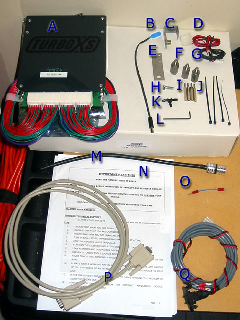
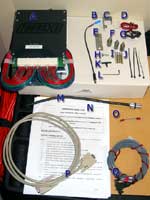
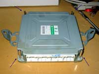
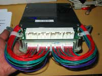
Here is my UTEC. I purchased it bundled
with the remote switch. Here is a list of the items you should receive.
A. The UTEC unit
B. 9V adapter - for running the UTEC outside of your car.
C. J bracket for kickplate - offsets the factory bolt location so
you can mount the kickplate after installation
D. Accessory/Spare Solenoid connector - this will not be used since
I am using the remote switch connector which has it's own accessory
connector
E. Automatic Boost Control (ABC) bracket - the ABC is optional for
the STi
F. Kickplate Standoff bolts - offsets the factory bolt locations so
you can mount the kickplate after installation
G. Ground wire - used to ground the UTEC to the car
H. J bracket bolt - for mounting the kickplate
I. ECU Standoff bolts - offsets the ECU screws so you can mount the
UTEC to the ECU
J. Zip ties - for use when mounting the ABC or whatever else you need
them for. |
|
 |
|
|
K. ABC Y piece - to split the tube to the ABC
L. Allen key - for mounting the ABC
M. ABC - the controller
N. Manual - read this!
O. I'm not really sure...
P. Serial cable - to hook up your laptop
Q. Remote switch - lets you change maps whenever you want.
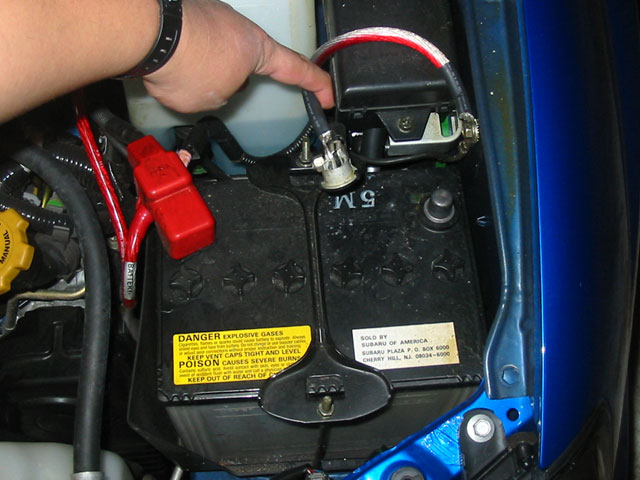
Once you have all the parts accounted for, disconnect the battery.
|
|
 |
|
Tools needed:
Screw drivers
Socket/Crescent wrenches - 10mm
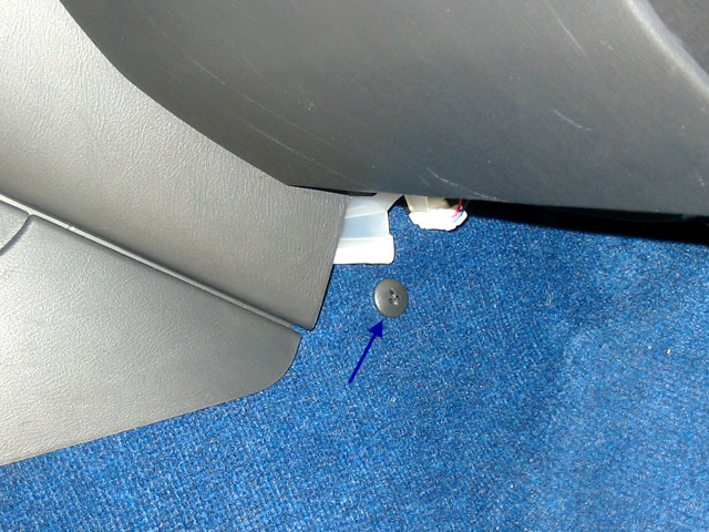
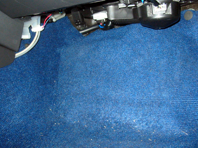
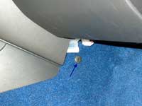
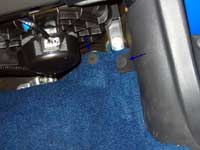
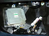
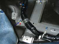
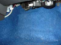
The ECU is located in the passenger foot well. Start by moving the
carpet. You'll need to undo a plastic screw on the left side. |
|
 |
|
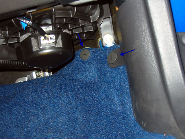
| And two more screws on the right side. |
|
 |
|
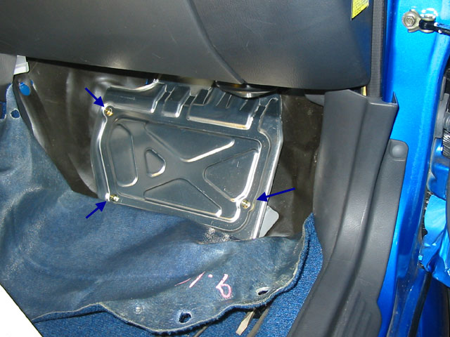
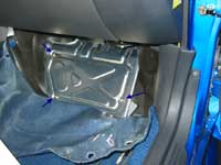
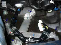
Wiggle the carpet out from the sides
and pull it down to expose the kickplate.
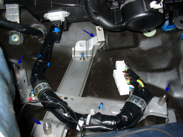
Remove the three bolts holding the kickplate down here. |
|
 |
|
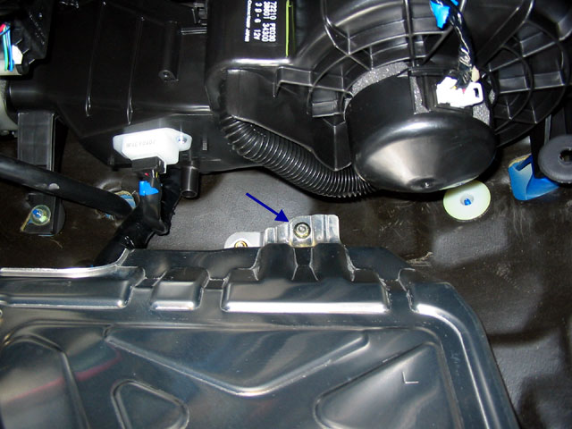
| Then remove the fourth bolt at the top
of the kickplate and remove the kickplate. |
|
 |
|
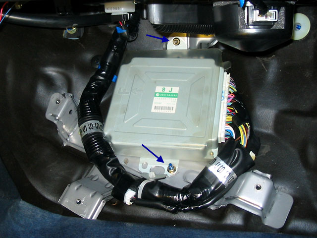
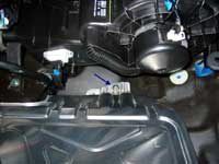
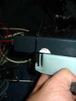
| This will expose the ECU. Remove the plastic
cover and discard. Remove the two bolts holding it down. |
|
 |
|
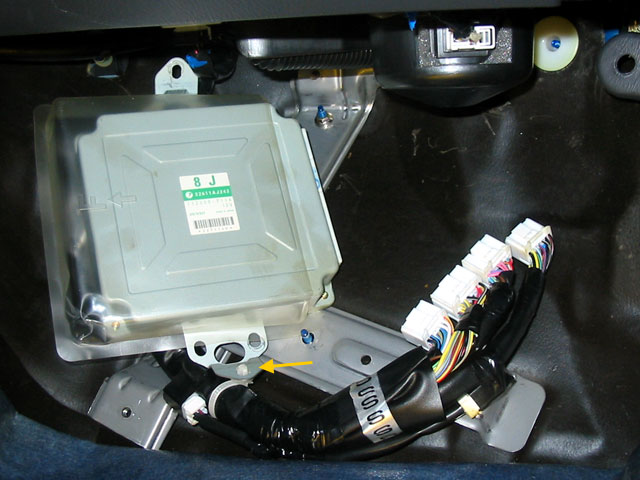
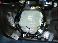
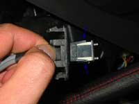
Remove the four wire harnesses on the
right. Do not pull on the wires. Instead, press the tabs in and use
a screw driver to pry the harnesses out.
After that, rotate the ECU so you can release the tab holding the
wires to the ECU (see yellow arrow) |
|
 |
|
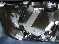
| Remove the ECU and you will see the X-bracket
that was holding it. |
|
 |
|
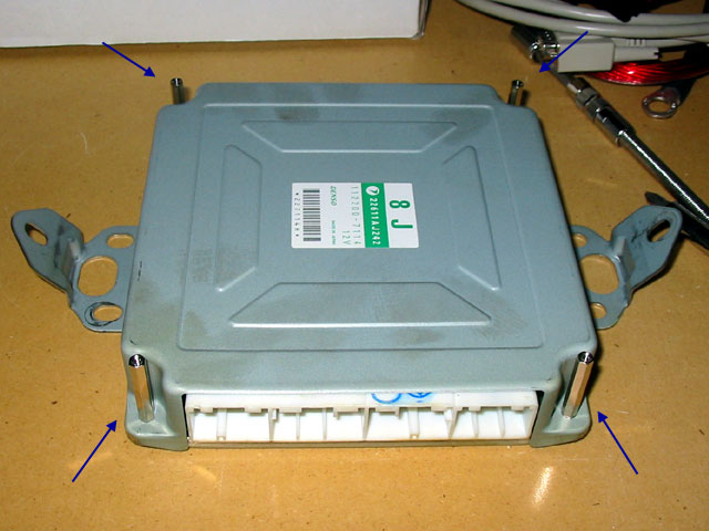
Take the ECU and remove the four screws
holding the metal cover down. Leave the metal cover in place and replace
the four screws with the ECU standoff screws provided.
|
|
 |
|
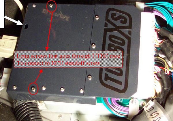
Place the UTEC on top of the ECU with
the wire harnesses on the same side. Use two of the screws removed
from the ECU to attach the harness side of the UTEC to the standoff
screws.
On the other side of the UTEC, the instructions mentioned using some
other "captive screws" but mine were apparently missing.
Here is what the installation is supposed to look like.
Thanks to DataDatum for this picture. |
|
 |
|
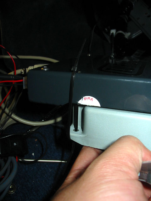
| Since my UTEC was missing the extra screws,
I had to remove two of the standoff screws and use zip-ties instead.
|
|
 |
|
Remove the wire harnesses from the UTEC.
As with the ECU, do not pull on the wires, but use a screw driver
to press the tab in and lever the harnesses out.
Connect the harnesses from the UTEC to the matching ECU ports. |
|
 |
|
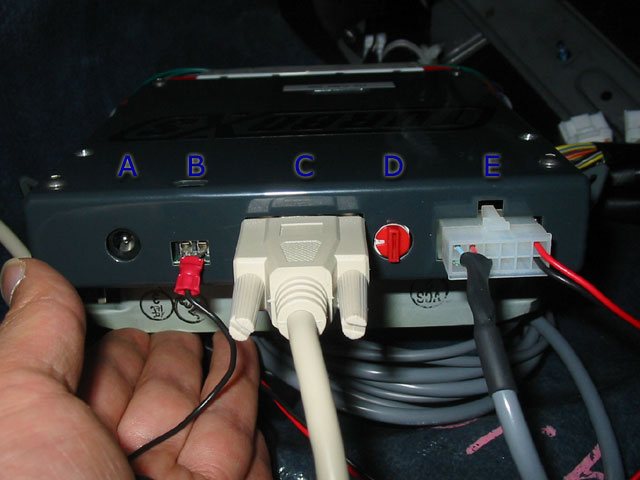
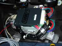
Bring the ECU/UTEC back to the car.
Note the external power source if you want to run off a 9V battery
(A)
Attach the spade end of the ground wire into the grounding point of
the UTEC and tighten the screws above to secure it (B).
Attach the serial cable (C).
Note the map selector switch (D). If using the remote switch, make
sure this is set to 0, otherwise set it to the map you wish to use.
If you plan to use the remote switch or the accessory connector, attach
it here (E). |
|
 |
|
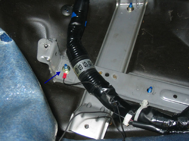
| Attach the round end of the ground wire
to one of the screws for the X-bracket. |
|
 |
|
|
Attach the J-bracket to the top bolt that held the kickplate on
using the original nut. Orient it so that the new hole provided
is higher than the original.
Attack the three kickplate offset screws to the original kickplate
mounting points
|
|
 |
|
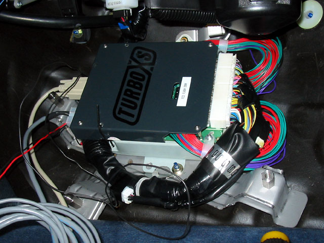
| Place the ECU/UTEC back into it's original
position and bolt it to the X-bracket, making sure that the cables
and wires are not stuck or tangled. |
|
 |
|
If you are planning to tune and are not
using the remote switch, don't re-attach the kick plate in case you
need access to the map selector switch.
Otherwise, tie up any loose wires (like the ground wire and accessory
wires) and re-attach the kickplate and replace the carpet
There will be a lump in the carpet because of the offset ECU/UTEC,
but after putting down your floor mats, most people won't notice.
Besides, what are you doing driving ballast, er, passengers, around
in your STi anyway? |
|
 |
|
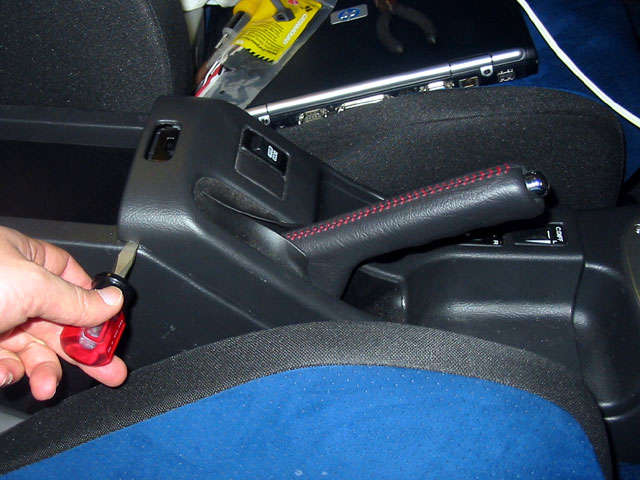
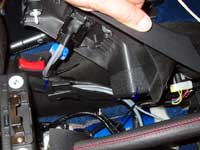
Next is the switch installation. If you
aren't using the remote switch, you can skip the next few steps.
The easiest place to mount the switch is the empty spot next to the
DCCD control (on 2004 models) on the center console. It will NOT fit
in the empty spots by the I/C spray on the driver's side dash, they
are too big.
To access the empty spot on the center console, remove the console
holding the DCCD control by pulling up on the front of the console
section. |
|
 |
|
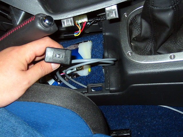
Then, using a screwdriver, pry up the
back of the console section.
Pull the parking brake up. It will be easier if it is pulled higher.
Pull the whole console section up and off the parking brake so it
is free. You will notice that there are two wire harnesses, one for
the DCCD switch and one for the DCCD mode selector.
Pop out the blank button from the back. |
|
 |
|
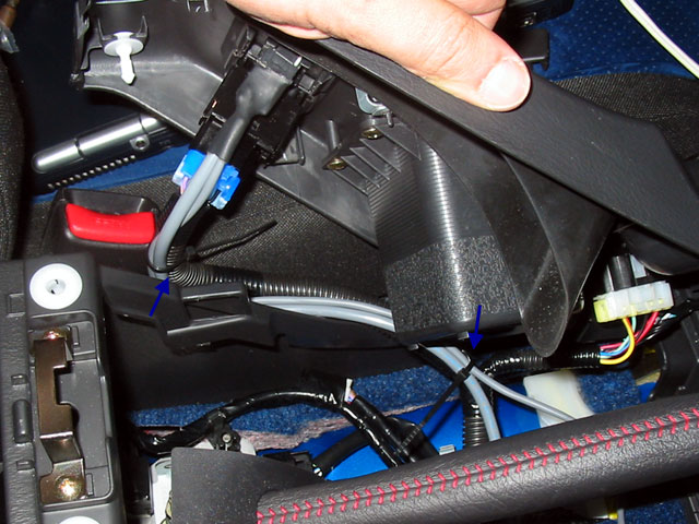
| Route the switch under the side of the
console and pull it through so that it follows the existing wire harnesses. |
|
 |
|
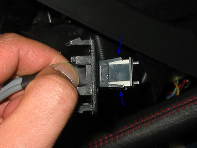
I found that the easiest way to get the
switch into the blank spot was to remove the actual switch from the
plastic button housing it is in. To do this, use a small screw driver
to press in the clips that hold it in place and push the switch through
the housing.
Now, push the switch, followed by the housing through the blank hole.
Re-assemble the switch/housing then fit it into the blank spot. |
|
 |
|
To make sure the wires aren't flopping
around, zip tie the wires to the existing harnesses.
Replace the console by fitting it back over the parking brake then
pushing the clips back into place. |
|
 |
|
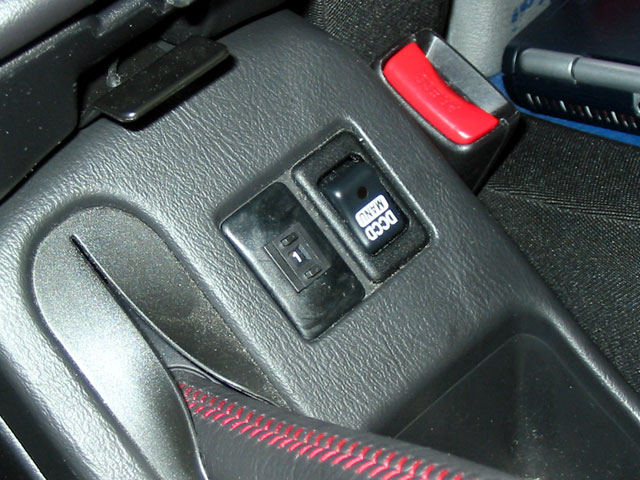
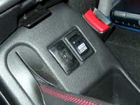
| Here is what the switch looks like when
it's done. |
|
 |
|
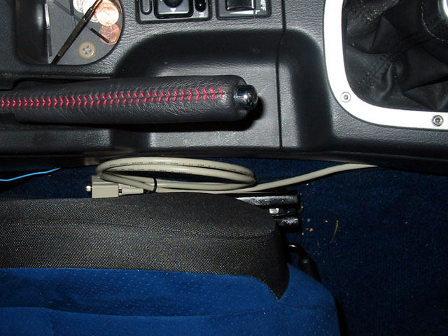
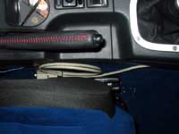
You'll also need to run the serial cable.
I tucked mine under the side of the console, but instead of running
it into the console, I just dropped it down to the side of the seat
so I can reach for it when I need to.
I am, however, considering cutting a hole into the armrest to hide
the switch and/or cable in there. |
|
 |
|
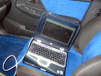
Run HyperTerminal on your Windows laptop
(usually in Accessories > Communications) and set it up according
to the UTEC Manual.
Connect the serial cable to your laptop and set the map selector switch
to 0 (stock).
Re-attach the car battery and turn the ignition to ON (don't start
it yet). Make sure you can connect to the UTEC and it behaves as explained
in the UTEC Manual.
If all is good, start the engine. Since it is in stock mode it should
not have any problems. If there are problems or the car feels funny,
call TurboXS! Otherwise, take it for a spin and make sure it's working
properly. |
|
 |
|
Then check out map 1 (TurboXS
tuned stock car). You can change maps while the engine is on and idling
though it may run rough while it switches. Also check out map 6 (valet
mode with limited boost and timing) and map 7 (security, the car cannot
be started).
Total Time: 90 minutes
Difficulty: Easy.
Verdict: I think the valet and security modes alone are worthwhile.
Otherwise, I can't really tell a difference on a stock car, but knowing
that I will be able to tune the car no matter what mods I get in the
future is really nice. |
|
| Coming Soon: Tuning the UTEC |
|
|
| |
|
|